Figure 1
Accutrak™ is designed to monitor car wash equipment. In order to do this, the system must be wired to the car wash equipment. This chapter will show how this is done.
When electrical power is connected to a carwash, there are several options available depending on the equipment in the carwash and the local electrical company. The first option to consider is the voltage. AC power is usually available from the pole in either 230VAC or 460VAC. The second option is single phase or three phase. Three phase power is not generally used by self serve car washes although some do use it if In-Bay Automatics are used.
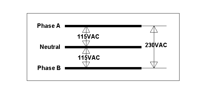
First lets consider the standard single phase 230VAC connection that is the most common. Three conductors are brought from the power company's pole into the car wash. One of these wires is the neutral and is connected to earth ground at the service entrance (circuit breaker box.) The other two wires are each 115VAC in relation to the neutral. However, these two wires are 180 degrees out of phase with each other. Thus if a voltmeter is placed between these two "hot" wires, it will read 230VAC. But reading from either to the neutral shows 115VAC. See Figure 1.

Figure 1
Inside the typical circuit breaker box there will be two copper bus bars; one for the A phase and one for the B phase. If a voltmeter is placed between these two bus bars it will read 230VAC. There is also a neutral bus bar that is generally located to the side of the breaker box and has many connection locations along it. All of the white insulated romex wires are connected to this neutral bus. The black insulated romex wires are connected to the individual circuit breakers.
The A and B bus bars are situated with regard to the breakers such that every other breaker contacts the A phase and the intervening breakers contact the B phase. When 230 volts is required, the electrician installs combined two section breaker, one section on the A phase and one on the B phase. Since the A and B phases are at 230 volts relative to each other, 230 volt power is available using this connection. On the other hand, for normal 115 volt connections only a single breaker connected to either the A or the B phase is used.
In the great majority of cases whether power comes from the A phase or the B phase does not matter. However, when connecting these different phases at a monitoring device, one must always remember that the two together are separated by 230 volts!

Figure 2
Figure 2 shows an outline drawing of the Accutraktm system. The enclosure is rated NEMA 12 drip proof not waterproof. Within the enclosure there is the rack which has a power supply plugged into the receptacle. A CPU (Central Processing Unit) card and as many as eight input cards are inserted into the rack. The CPU card (which has a blue ejector tab) is always inserted in the left most slot of the rack. This slot is labeled "CPU". The input cards are inserted in the slots labeled "Slot 1", Slot 2", etc.
Accutrak™ requires two amperes of 115VAC current that should come from a separate breaker or switch. This power must not dip lower than 103.5 nor rise above 126.5 volts AC. Operation outside of this range may cause damage to Accutrak™ that is not covered by our warranty. The system has a built-in surge suppressor that is designed to handle normal power surges. It is not designed to handle lightening. If Accutrak™ is to be installed at a location that is subject to near strikes by lightening, then a local expert should be consulted for additional protection which may be required. Lightening damage is not covered by our warranty.
A green THHN AWG 6 or larger wire should be used to connect the system to earth ground. The main purpose of this ground is to maintain the noise immunity of the system. Secondarily it serves to meet the requirements of the National Electrical Code. Thus it is extremely important to ensure a solid connection to and earth ground. If city water is used then an adequate connection can usually be made to a metal water main. The electrician should buff the water pipe first and then use an approved clamp to connect the ground wire securely.
If city water is not available, then it may be necessary to drive a grounding rod into the earth. If a grounding rod is used it must reach the water table.
Each input card contains eight inputs. Each input may be any AC voltage from 24 to 125 or a DC voltage from 24 to 100 volts. Although it is possible to put different voltages on the same card, it is not advisable to do so. Figure 3 shows an outline view of the input card.
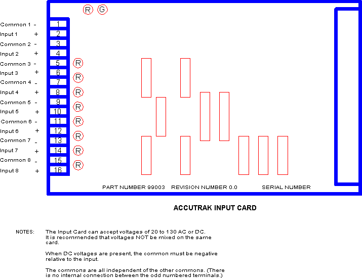
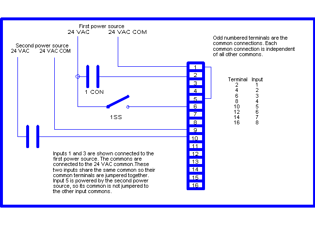
Figure 4 shows three contacts correctly wired to an input card.
For those not familiar with the general theory of electricity, it might help in understanding electrical circuits to know that in order for any electrical apparatus to work, there must exist a continuous and uninterrupted path from the "hot" lead to the "common" lead. In a house, the "hot" lead going to a light is interrupted by a switch. Thus when the switch is closed, the light is on, but when the switch is open, the path for electrical current flow is broken and the light is off. The same requirement for a continuous path exists when connecting to Accutrak™
With low amperage transistor circuits, leakage current is a fact of life whenever two or more solid state devices are tied together in the same circuit. The discussion that follows is not intended to be an exactly correct description of the physics that controls, but instead is intended for the understanding of those without benefit of a technical background.
The basic problem that occurs when two solid state or transistor devices are connected in the same circuit is that one of them is kept energized by the leakage current from the other. Transistors are not able to totally stop the flow of electrons in their de-energized state. In normal practice, the ratio of the conducting state current to the non-conducting state current is greater than 10,000 to 1. However, there is always a small amount of current passing through the transistor even in the non-conducting state. If this current is high enough it can keep a sensitive circuit such as the one that exists in the Accutrak™ turned on.. (Solid state circuits may require a relatively high voltage to turn on, but then will stay turned on until the voltage drops significantly below the turn on value.)
The problem of leakage current can generally be solved by using blocking diodes. (A diode is an electrical one way or check valve. Electric current will only flow in one direction through a diode.) Figure 5 shows a typical car wash coin acceptor and timer connected to an Accutrak™ input without using a diode. Figure 6 shows the same setup with a diode installed. Note the direction of the diode. This is critical. If the diode is installed backwards then neither the Accutrak™ nor the timer will work. (A diode has a stripe around the end that corresponds to the tip of the arrow on the schematic representation.)
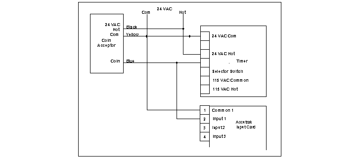
In order to count the coins, the output of the coin acceptor must be connected to Accutrak™. But in order to control the timer, the coin pulses must be sent to the timer as well. If the timer is a solid state device, (and more and more of them are,) then the leakage current of the timer may keep the Accutrak™ input energized after the coin is dropped. This causes all coins but the first to be missed.
It is instructive to look at this example in more detail. Recalling Figure 3 the Accutrak™ input has an internal diode that points toward the input terminal. (A diode only allows current to flow from positive to negative in the direction of the diode arrow.) This means that current flows through the detector circuit only when the input terminal is negative referenced to the common terminal. In Figure 6 the coin acceptor causes the blue wire to go negative when it accepts a valid coin. In the timer, current flows out of terminal 4 and "sinks" in the coin acceptor. Simultaneously current also flows out of terminal 2 on the Accutrak™ input card causing Accutrak™ to count the coin. Then the problem of leakage current arises in Figure 4. Terminal 4 of the timer becomes a lower voltage than terminal 2 of the Accutrak™. Thus current continues to flow through the Accutrak™ circuit and only one coin is counted. In this case Accutrak™ for effective purposes ceases to work.
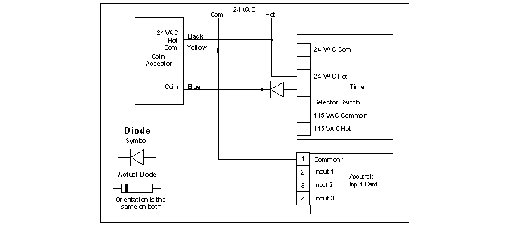
Figure 6 shows a diode inserted between the Accutrak™ connection and the timer terminal 4. When a coin is accepted the blue wire on the coin acceptor still goes negative. Both the timer and Accutrak™ see this change and both began to conduct current. Then the coin passes and the blue wire on the coin acceptor goes positive again. This time the added diode prevents any current flow from Accutrak™ to the timer. (When two diodes are in the same circuit with their arrows pointing at each other current flow is impossible. Current flow is also impossible if two diodes are in the same circuit with their arrows pointing away from each other. Current can flow only when the arrows of the diodes are pointing in the same direction.)
We have been gathering data on various coin acceptor / timer combinations for several years. We have consolidated our knowledge into specific drawings contained in Appendix C to this manual. If you run into a different combination of coin acceptor and timer, we will gladly find the correct connections for you to use if you will send one of each to us freight prepaid. We will return the units to you freight prepaid together with a drawing showing the proper connections. In addition we will add this combination to future revisions of this manual.
Now that we have discussed the physical aspects of connecting the inputs to car wash devices, lets turn our attention to the data collecting process; that is, how the data is stored and used by the system.
Each input can be used in one of three different ways:
note: The Accutrak™ input is energized when the input is less negative than the common connector for that input.
The count mode is useful for keeping track of coins, number of customers, and similar events. Generally coin acceptors are going to be wired up to inputs that we will configure in the software setup as counters. (N.b., we do not have to worry about whether we are going to count or time or date/time stamp input data at the time we are doing the wiring. We wire the inputs first and then we configure the software to accomplish what we wish to do.)
The timer mode is useful for timing events such as operating times on the high pressure pumps. This time data can be very useful in establishing a preventative maintenance program that works.
The date/time stamp is useful for tracking when an event occurred. When was the last time the equipment room door was opened? When was Bay 4 last used?
The count mode is used to count coins, numbers of washes, etc. The Accutrak™ counter is much like the gallon counters that are used with most gasoline pumps. These counters count up continually. In order to know the daily gallonage, the gas station owner records the pump readings daily. Accutrak™ is going to do the same sort of recording except the office computer in conjunction with the Accutrak™ will collect and record the data automatically. For example, a coin acceptor is connected to an Accutrak™ input. Every time a coin is accepted, the Accutrak™ counts it. On a daily basis the owner calls up each Accutrak™ and downloads the data into the office computer. There the Accutrak™ program subtracts the previous count from the current count and thus determines the coins collected today.
Coins are an obvious thing to count. Bills accepted by bill changers, washes by type and number of vehicles are some examples of items some owners have chosen to count.
Keeping track of total operating times on high pressure pumps is a fairly obvious use of this mode of operation. The Accutrak™ stores the total time as with the count data. Again just like the count data, the operator downloads the timer data each day. The Accutrak™ program records the total time and subtracts the old data from the new to obtain the current days time.
The timer mode can be used to determine the approximate average time per customer. This is accomplished by connecting a counter and a timer to the selector switch. Since most timers these days have a last minute alert feature, most customers can be presumed to keep the timer going rather than having to meet the coins to start a second time. Thus the counter is only going to count once per customer. On the other hand, the timer is going to keep collecting time as long as the bay is active. If the total time is divided by the total counts then the time per customer is the result.
(The time per customer can be very useful in evaluating how to market the car wash. If the average time per customer is low then more revenue can be generated by showing customers how to use the tire cleaner, how to use the foaming brush, etc. By giving the customer an understanding of the features of the car wash, the customer uses more features and thus remains in the bay longer spending more money. If the average time per customer is high, then more customers have to be recruited in order to enhance revenue. The whole point of this discussion is that by knowing the average time per customer, the owner knows whether to spend money and time to train the existing customers or whether to start an advertising campaign.)